メニュー
| ▼ アクセス(地図)
▼ Windowsアプリ開発 ▼ マイコン開発 ▼ CGI・PHP制作 |
▼ サイトマップ(全投稿記事)
▼ タイトル(画像一覧) ▼ 事業内容 |

お問い合わせメールフォームが開きます。
2008年08月13日
Interface 9月号(ColdFire)でエレキー

エレキープロジェクト(?)第3弾
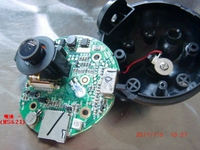
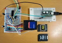
Interface 9月号(ColdFire・MCF52233付録基板)でエレキーを試作中です。

配線は、下記の写真のように基板に直接半田付けです。
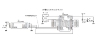
ポート配置は下記のような感じです。
PORTLD0 (44Pin) // --> 動作確認用LED(基板付属のもの)
PORTLD2 (42Pin) // --> Buzzer出力(発振回路内臓タイプ)
直接駆動不可(Trバッファ要)
PORTLD3 (36Pin) // --> Dot入力 (要PU抵抗)
PORTLD4 (31Pin) // --> Dash入力 (要PU抵抗)
AN0 (55Pin) // --> 速度調整VR
ポートを含むCPUのマニュアルは、freescaleのサイトにpdfがあります。
http://www.freescale.com/files/32bit/doc/ref_manual/MCF52235RM.pdf
PU(プルアップ抵抗・10kΩ)は下記のような感じで半田付けしました。

ソフトウエアは現在製作中です。
開発ツールは、「ColdFire用GCC&GDB」
(インストール方法は、http://www.cqpub.co.jp/interface/ や Cgywinのサイトをご参照ください。)
とりあえず、CQ出版社提供LED点滅サンプルプログラムの動作確認済みです。
このサンプルについては、134ページに少し解説がありますし、10月号で詳しく説明があるようです。
ポートの入力判断は下記のようになります。
1: 今回使用するポートは汎用とする("0"のまま)
MCF_GPIO_PLDPAR = MCF_GPIO_PORTLD_PORTLD1
| MCF_GPIO_PORTLD_PORTLD5
| MCF_GPIO_PORTLD_PORTLD6;
2: 今回使用する出力ポートの設定("1"で出力)
MCF_GPIO_DDRLD = MCF_GPIO_DDRLD_DDRLD0
| MCF_GPIO_DDRLD_DDRLD2;
3: 今回使用する入力ポートの設定
"Port Pin Data/Set Data Registers" を下記のように
ヘッダファイルへdefine しておく。
#define MCF_GPIO_DSDRLD (*((volatile unsigned char*)(IPSBAR + 0x100045)))
4:判断方法は下記のような感じで。
if (!(MCF_GPIO_DSDRLD & MCF_GPIO_PORTLD_PORTLD3))
動作ムービーは下記からご覧いただけます。
http://micom.hamazo.tv/e1600471.html
ソースコードはこちら (A/D変換処理は未確認です。)
//----------------------------------------------------------------------------
//
// Simple Elekey Program by ColdFire
//
// DESCRIPTION:
// Elekey program Code for CQ出版Interface Coldfire(CQ-FRK-MCF52233)基板
//
// Editer: M.Utsunomiya
// Date: 2008/12/27
//
// Copyright (C) Hamamatsu-micom.com 2008. All rights reserved.
//
//----------------------------------------------------------------------------
//----------------------------------------------------------------------------------------
// ポート説明
//----------------------------------------------------------------------------------------
//
// Port Output Data Registers (PORTn)
// Port Data Direction Registers (DDRn)
// 1: DDRnx is configured as an output
// Port Pin Data/Set Data Registers (SETn)
// 1: Port n pin x state is 1 (read); writing a 1 sets the corresponding bit to 1
// Dual Function Pin Assignment Registers (PARn)
// 1: Pin assumes its primary function
//----------------------------------------------------------------------------------------
// PORTLD0 // ACTLED --> 動作確認用LED
// PORTLD1 // LNKLED --> そのまま
// PORTLD2 // SPDLED --> Buzzer出力
// PORTLD3 // DUPLED --> Dot入力
// PORTLD4 // COLLED --> Dash入力
// PORTLD5 // RXLED --> そのまま
// PORTLD6 // TXLED --> そのまま
//----------------------------------------------------------------------------------------
//----------------------------------------------------------------------------
/*
* CPU固有レジスタ定義
*/
//----------------------------------------------------------------------------
#include "m5223x.h"
//----------------------------------------------------------------------------
/*
* ユーザメモリ定義
*/
//----------------------------------------------------------------------------
unsigned long write_data_size;
volatile int Int_Count;
//----------------------------------------------------------------------------
/*
* 外部関数定義
*/
//----------------------------------------------------------------------------
extern unsigned long bios_call(unsigned long func, unsigned long arg0, unsigned long arg1, unsigned long arg2, unsigned long arg3);
//----------------------------------------------------------------------------
/*
* タイマへの入力クロックの分周比設定 (f/8でカウント)
*/
//----------------------------------------------------------------------------
#define TCR_CKS 0x0
//----------------------------------------------------------------------------
/*
* タイマに供給されるクロック周波数[kHz] (60MHz/2 = 30MHz)
*/
//----------------------------------------------------------------------------
#define TIMER_CLOCK (25000)
//----------------------------------------------------------------------------
/*
* タイマ値の内部表現の型
*/
//----------------------------------------------------------------------------
typedef unsigned short CLOCK;
//----------------------------------------------------------------------------
/*
* タイマ値の内部表現とミリ秒・μ秒単位との変換
*
*/
//----------------------------------------------------------------------------
#define TO_CLOCK(nume, deno) (TIMER_CLOCK * (nume) / (deno))
#define TO_USEC(clock) ((clock) * 1000 / TIMER_CLOCK)
#define CLOCK_PER_TICK ((CLOCK) TO_CLOCK(TIC_NUME, TIC_DENO))
#define MCF_INTC0 (IPSBAR + 0x0C00)
#define MCF_INTC1 (IPSBAR + 0x0D00)
#define MCF_INTC_IMRL(ch) (ch + 0x0c)
#define MCF_INTC_IMRH(ch) (ch + 0x08)
#define MCF_INTC_ICR(ch, n) (ch + 0x40 + n)
#define MCF_INTC_IMRH_ALL (0x00000000)
#define MCF_INTC_IMRL_ALL (0x00000001)
#define TBIT_TT0 (55 - 32)
#define TBIT_TT1 (56 - 32)
//----------------------------------------------------------------------------
// Define Code Parameter
//----------------------------------------------------------------------------
#define PARA_ALL_OFF 0x00
#define PARA_DOT_ON 0x01
#define PARA_DOT_OFF 0x02
#define PARA_DASH_ON 0x03
#define PARA_DASH_OFF 0x04
#define LIMIT_VALUE 0x03
#define LIMIT_VALUE2 0x02
#define MAX_SPEED 80
#define MIN_SPEED 20
#define CODE_OUTPUT_ON (MCF_GPIO_PORTLD |= MCF_GPIO_PORTLD_PORTLD2)
#define CODE_OUTPUT_OFF (MCF_GPIO_PORTLD &= ~MCF_GPIO_PORTLD_PORTLD2)
#define DOT_INPUT_ON (!(MCF_GPIO_DSDRLD & MCF_GPIO_PORTLD_PORTLD3))
#define DASH_INPUT_ON (!(MCF_GPIO_DSDRLD & MCF_GPIO_PORTLD_PORTLD4))
//----------------------------------------------------------------------------
// Define User Memory
//----------------------------------------------------------------------------
unsigned int ParaTime;
unsigned char AdcData;
unsigned char TimerTest;
unsigned char Timer100ms;
unsigned char ParaCode;
unsigned char CntDotOn;
unsigned char CntDashOn;
unsigned char CodeBuff;
unsigned char CodeData;
unsigned char CntP10_On;
unsigned char CntP10_Off;
unsigned char P10_buf;
//----------------------------------------------------------------------------
/*
*
*/
//----------------------------------------------------------------------------
int debug_putc(int c)
{
return (int)bios_call(0, c, 0, 0, 0);
}
//----------------------------------------------------------------------------
/*
*
*/
//----------------------------------------------------------------------------
int int_vcs(int vecno, void* p)
{
return (int)bios_call(8, vecno, p, 0, 0);
}
//----------------------------------------------------------------------------
/*
* puts()
*/
//----------------------------------------------------------------------------
int puts(char *str)
{
int i;
for (i = 0; ;i++) {
if (str[i])
debug_putc(str[i]);
else
break;
}
return 0;
}
//----------------------------------------------------------------------------
// Check Encoder port
//----------------------------------------------------------------------------
void ChkEncoderPort()
{
}
//----------------------------------------------------------------------------
// Check ADC port
//----------------------------------------------------------------------------
void ChkAdcPort()
{
int i;
int tmpData;
//InitAd(0x70);
MCF_ADC_CTRL1 = 0x20;
for (i = 0; i <1000; i ++) ;
//tmpData = 0x3F & (MCF_ADC_ADRSLT0 >> 9);
tmpData = (MCF_ADC_ADRSLT0 >> 3);
if (tmpData)
AdcData = (char)tmpData;
else
AdcData = MIN_SPEED;
// AdcData = 0x1F & (char)(MCF_ADC_ADRSLT0 >> 9);
/*
while (1) {
if (MCF_ADC_CTRL1 & 0x4000)
{
AdcData = MCF_ADC_ADRSLT0 >> 7;
break;
}
}
*/
}
//----------------------------------------------------------------------------
// Set Output port
//----------------------------------------------------------------------------
void SetOutput()
{
if ((ParaCode == PARA_DASH_ON) || (ParaCode == PARA_DOT_ON)) {
CODE_OUTPUT_ON;
MCF_GPIO_PORTLD &= ~MCF_GPIO_PORTLD_PORTLD0; // LED On/Off
}
else {
CODE_OUTPUT_OFF;
MCF_GPIO_PORTLD |= MCF_GPIO_PORTLD_PORTLD0; // LED On/Off
}
}
//----------------------------------------------------------------------------
// Check Input port
//----------------------------------------------------------------------------
void ChkInputPort()
{
// for Dot
if (ParaCode != PARA_DOT_ON) {
if (CntDotOn < LIMIT_VALUE) {
if (DOT_INPUT_ON)
CntDotOn ++;
else
CntDotOn = 0;
}
}
// for Dash
if (ParaCode != PARA_DASH_ON) {
if (CntDashOn < LIMIT_VALUE) {
if (DASH_INPUT_ON)
CntDashOn ++;
else
CntDashOn = 0;
}
}
}
//----------------------------------------------------------------------------
// Set Parameter Dash
//----------------------------------------------------------------------------
char SetParaDash()
{
if (CntDashOn >= LIMIT_VALUE) {
CntDashOn = 0;
ParaCode = PARA_DASH_ON;
ParaTime = (AdcData * 3);
return 1;
}
return 0;
}
//----------------------------------------------------------------------------
// Set Parameter Dot
//----------------------------------------------------------------------------
char SetParaDot()
{
if (CntDotOn >= LIMIT_VALUE) {
CntDotOn = 0;
ParaCode = PARA_DOT_ON;
ParaTime = AdcData;
return 1;
}
return 0;
}
//----------------------------------------------------------------------------
// 1msec Timer Interrupt routine
//----------------------------------------------------------------------------
void intsrv_tim(void)
{
TimerTest --;
if (TimerTest == 0) {
TimerTest = AdcData; // for Test
MCF_GPIO_PORTLD ^= MCF_GPIO_PORTLD_PORTLD0; // LED On/Off
}
if (ParaTime != 0) {
ParaTime --;
if (ParaTime == 0) {
if (ParaCode == PARA_DOT_ON) {
ParaCode = PARA_DOT_OFF;
ParaTime = AdcData;
}
else if (ParaCode == PARA_DASH_ON) {
ParaCode = PARA_DASH_OFF;
ParaTime = AdcData;
}
else if (ParaCode == PARA_DOT_OFF) {
if (!SetParaDash())
ParaCode = PARA_ALL_OFF;
else {
CodeBuff <<= 1;
CodeBuff |= 1;
}
}
else if (ParaCode == PARA_DASH_OFF) {
if (!SetParaDot())
ParaCode = PARA_ALL_OFF;
else
CodeBuff <<= 1;
}
else {
ParaCode = PARA_ALL_OFF;
CodeData = CodeBuff;
}
SetOutput();
}
}
ChkInputPort();
if (ParaCode == PARA_ALL_OFF) {
if (!SetParaDot()) {
if (SetParaDash())
CodeBuff = 0x03;
}
else
CodeBuff = 0x02;
SetOutput();
}
ChkEncoderPort(); // Check Encoder port
}
//----------------------------------------------------------------------------
/*
* タイマ割込み
*/
//----------------------------------------------------------------------------
int __attribute__((interrupt_handler)) timer_handler()
{
Int_Count++;
MCF_PIT0_PCSR = MCF_PIT0_PCSR;
intsrv_tim();
}
//----------------------------------------------------------------------------
/*
* メイン
*/
//----------------------------------------------------------------------------
int main()
{
// エレキー用ユーザメモリの初期化
CntDashOn = 0;
CntDotOn = 0;
ParaTime = 0;
ParaCode = PARA_ALL_OFF;
AdcData = MAX_SPEED;
// Dual Function Pin Assignment Registers (1:Primary function)
MCF_GPIO_PLDPAR = 0x00;
MCF_GPIO_PLDPAR = MCF_GPIO_PORTLD_PORTLD1 // LNKLED
| MCF_GPIO_PORTLD_PORTLD5
| MCF_GPIO_PORTLD_PORTLD6;
MCF_GPIO_PNQPAR = 0x00000100; // A/D port0
// Data Direction Registers (1:output)
MCF_GPIO_DDRLD = MCF_GPIO_DDRLD_DDRLD0
| MCF_GPIO_DDRLD_DDRLD2;
MCF_GPIO_PORTLD = 0x00;
int_vcs(119, timer_handler);
Int_Count=0;
/* タイマ割込みの割込みレベルを設定し,要求をクリアした後,
* マスクを解除する.
*/
(*(unsigned char*)(MCF_INTC_ICR(MCF_INTC0, 55))) = (((5) << 3) | (5));
(*(unsigned long*)MCF_INTC_IMRH(MCF_INTC0)) &= ~(1 << (TBIT_TT0));
MCF_PIT0_PCSR = (unsigned short)(MCF_PIT_PCSR_OVW | MCF_PIT_PCSR_PIF | MCF_PIT_PCSR_RLD);
MCF_PIT0_PMR = (unsigned short)0xFFFF;
MCF_PIT0_PCNTR = 0x0000;
MCF_PIT0_PCSR |= MCF_PIT_PCSR_PIE; //割り込み許可
MCF_PIT0_PCSR |= MCF_PIT_PCSR_EN;
while (1) {
if (ParaCode == PARA_ALL_OFF) {
ChkAdcPort(); // Check ADC port
}
}
return 0;
}
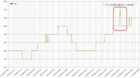
スクイズ機能で不用意にキーがメモリされてしまい、速度を上げると余計な符号が出る不具合があります。


この記事へのコメント
あはは、やっぱりこれでもあくまでもエレキーなんですね。:-)
Posted by ながやま at 2008年08月13日 20:00
ながやまさん
こんばんは。
そうなんです。
まずは、環境になれるのが第一目的で、そのサンプルが「エレキー」なんです。
シリーズは続きますよ ^^;
こんばんは。
そうなんです。
まずは、環境になれるのが第一目的で、そのサンプルが「エレキー」なんです。
シリーズは続きますよ ^^;
Posted by 宇都宮 at 2008年08月13日 21:43
 at 2008年08月13日 21:43
なるほど、まずはエレキーでジャブってことなんですね。PSoCでもやってるみたいですもんね。
Posted by ながやま at 2008年08月13日 22:46
これって SilentCで開発しています?
本格的にやろうとすると BDMデバッガが必要になりますよね。
本格的にやろうとすると BDMデバッガが必要になりますよね。
Posted by ビーコン菅原 at 2008年08月14日 02:55
ビーコン菅原さん
おはようございます。
雑誌に書かれているSilentCライブラリ関数を見たのですが
タイマイベントの扱いが良くわからないので、あきらめ、通常のCで作成しています。
付属マイコン基板にはGDBスタブが書き込まれているので
イーサネット経由でGDBデバッグが可能です。
おはようございます。
雑誌に書かれているSilentCライブラリ関数を見たのですが
タイマイベントの扱いが良くわからないので、あきらめ、通常のCで作成しています。
付属マイコン基板にはGDBスタブが書き込まれているので
イーサネット経由でGDBデバッグが可能です。
Posted by 宇都宮 at 2008年08月14日 08:37
at 2008年08月14日 08:37